The schematics
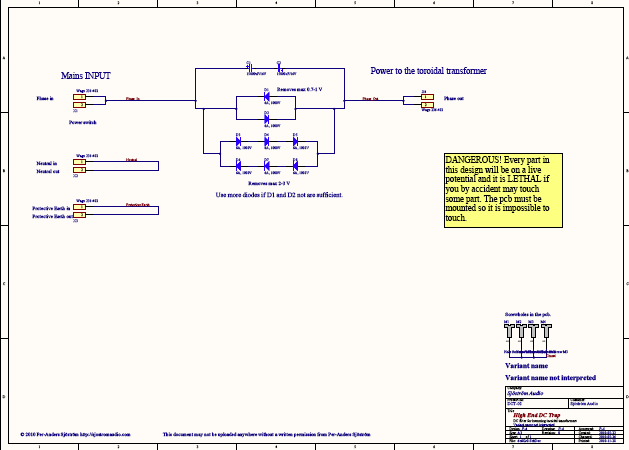
Click on the picture to get a larger view. The picture shows the schematics of the amp. Of course you can't use it for anything except for an overview. Please download the pdf-file instead if you want to see the details.
WARNING - CAUTION
As you can see at the picture the pcb will be at mains potential and therefore lethal. You must insure that this pcb is well protected against unintentional touching. All parts are dangerous to touch when the mains is switched on.
Circuit description
This design is very simple, just a couple of diodes and capacitors. The purpose of the diodes is to limit the DC voltage across the caps, especially at high load and at power on. I have made room for two options in terms of DC level. Use only D1 and D2 if this is sufficient. Max voltage across the cap will be 0.7 volts. If you have no opportunity or won't risk anything, go for D3-D8 right away. The only disadvantage is a slightly higher cost. If you of some reason want to go from two diodes to six, just cut away D1 and D2. Don't try to desolder. You will only damage the pcb.
The capacitor impedance determined by:
Z = 1/(2*pi*f*C)
where
f = mains frequency, 50 or 60 Hz
C = capacitance in Farads
Maximum current without passing the diodes:
Max Irms = 0.7*U*2*pi*f*C
where
U = the voltage when current is flowing through the diodes which also can be tranzils. In my case 0.7 or 2.1 Volts
C = capacitance. If two 10000 uF are used the capacitance will be 5000 uF.
f = mains frequency, 50 or 60 Hz
X1 and X4 are 2-pole just because they are separated and the connector has two poles. No need for the extra pole really.
I have added room for three wires in and three wires out. Neutral and Protective Earth can be connected also just as a joint between incoming mains cable and the internal wiring.
| Terminal | Pin | Name | Incoming power | To transformer | Notes |
| X1 | 1 | Phase in | X | - | |
| X1 | 2 | Phase in | - | - | Not used, only for mechanical stability. |
| X2 | 1 | Neutral in | X | - | |
| X2 | 2 | Neutral out | - | X | |
| X3 | 1 | Protective earth in | X | - | |
| X3 | 2 | Protective earth out | - | X | Connected to chassis. The incoming wire could also be connected directly to the chassis. |
| X4 | 1 | Phase out | - | X | |
| X4 | 2 | Phase out | - | - | Not used, only for mechanical stability. |
