A complete product, a mono block
Click on the picture to get a larger view.
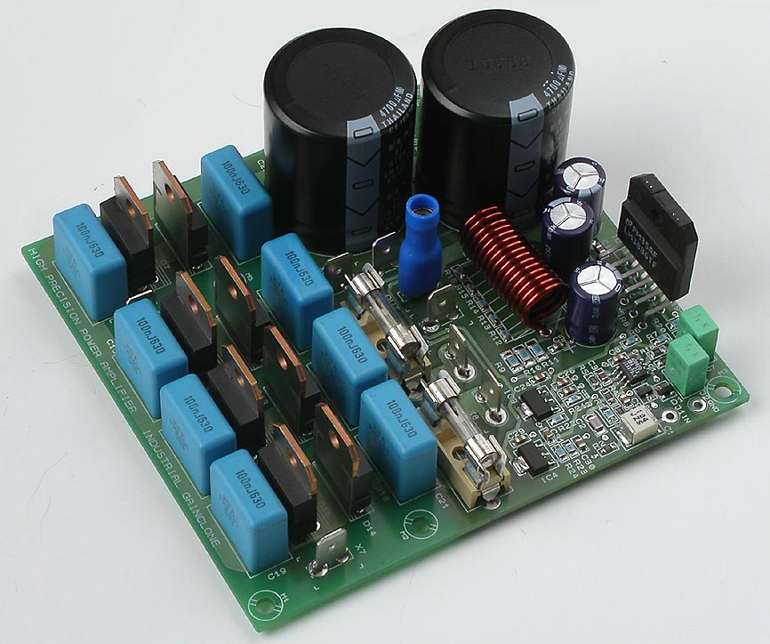
The goal is a complete product, just add two windings with AC, signal in and speaker out and a cute small pcb.
Please download the AN-1192 and try to understand this very good application note. Much of this design is based on this application note. I have made some adjustments but the basic idea is very good.
Overture_Design_Guide13.xls (and instructions for the file) is a very good tool when you want to estimate needed transformer and other power supply parts, heatsink etc. If you can't get these files, send me a message and I'll send those to you.
The design consists of an input buffer, the power IC, LM3886, an extremely high performing DC-servo, a power supply and a rectifier bridge. The thing which is missing is only a transformer.
Lower distortion
Inverting configuration is chosen for the LM3886 and the reason for this is ten (at least 2-5) times lower distortion. Those people which have problems with that may switch the speaker cables.
Pop and click free
Since the basic design already is tested in my other Gainclone project I'm quite confident that this very cute little pcb will perform to full satisfaction. The first listening impressions points in that direction. One problem that many Gainclone builders experience is DC shifts, pops, hump, click etc at power down and power on. This design is totally pop free! The secret is that the buffer works low below +- 12 volts where the undervoltage protection works for the LM3886. LM3886 has also an effective mute function which ensures a smooth startup.
Low impedance drive
The LM3886 is driven from a low impedance buffer which makes it possible to use rather low resistor values for the feedback. This is good because all stray capacitances will have less influence. The feedback network gets more ideal, more resistive, higher up in frequency. The usage of SMD resistors makes this even better. This is a positive thing for stability, clean behavoir and performance in general.
The input buffer
AD8620, is chosen as a buffer because it's a really, really good opamp. The most impressing feature besides the sound quality is the extremely low offset voltage, around 70 µV! The same opamp works also as DC servo which makes it in world's class, an extremely high performing DC servo. This DC servo is the best world has seen so far. Am I wrong?
The buffer accomplish also an effective buffering and isolation from the signal source. This means low interaction between power amp and signal source. Since a non-inverting buffer is used the input filter can be taylored to suit your demands in any way you like. The gain is minimal (slightly over 1) but can be tuned to any value above 1.
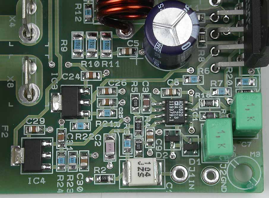
Click on the picture to get a larger view. Detail of the input buffer
Power supply
As you may have noticed I have not chosen to have each rail voltage on each side which is common pratice. I have chosen to have all the power at the left side of the pcb and have sensitive signals on the right side. The pcb gets a bit "unbalanced" to the looks but electrically it feels better. As you also can see I have made an option for "plain" electrolytic caps and for heavy duty types with snap-in pins. I have also high performance decoupling accomplished by SMD caps of 100 nF very close to the power supply pins of the LM3886 and the caps go directly down to groundplane. Half the success is proper supply voltage which is not very easy to get unless you have a good pcb with groundplanes.
Rectifier bridges
I really recommend you to have two separate windings connected to two separate rectifier bridges. You can either have really big TO247 diodes which costs a lot and may be overkill technically but you can also have TO220 types which are much cheaper and more "normal" and definitely sufficient. Both diode types can be attached to a heatsink. The gap between the diode rows is for this purpose but please beware of that the diodes needs insulation.
You can also use only one rectifier bridge. See a special intruction for this. Then you will not use X3 and X7 but X5 and X6 will be used instead.
Transformer
The design is a mono block, meaning you must have one transformer to each pcb. Suitable size is 80 VA as minimum, 100-160 VA as normal and 225-300 VA is "serious". 400 VA and above is overkill. Recommended voltage is 2 x 22-28 VAC. 2 x 30 VAC gives you a voltage just at the edge of what the LM3886 can take. I don't recommend it.
