The background
This design has been known at www.diyaudio.com and elsewhere and it has been bescribed thoroughly in couple of articles in The Audio Amateur and also in other magazines, like EDN. The design presented below is a developed/altered version (not necessarily better) and not identical to the one in the articles nor to the pcb from Audio Express. Some of the changes has Andrew L Weekes done and some have I done.
Changes Walt Jung -> Andrew Weekes
Andrew added the preregulator and redesigned the pcb and added a starground in a more clear way. He also made a higher quality pcb with thicker copper.
Changes Andrew Weekes ->Per-Anders Sjöström
- Added all parts around the preregulator.
- Added component print on the pcb.
- Added a footprint for SO08 opamps.
- Added compensation for the opamp.
- Added a footprint both LM431 and LM329.
- Added footprints for SOT23 transistors.
- Added trimming facilities, both with fixed resistors and with trimpots.
- 4 layer pcb with 70 um copper resulting in 140 um for all high current traces and a good grounding.
- Added parts for tying the sense inputs to the outputs.
- Added solder pads for the sense inputs if you wanted to "park" them and left them unused.
- Added option for using higher voltage than the max supply voltage for the opamp.
- Added option for feeding the opamp from before the pass transistor enabling a very low output voltage using opamps with not low enough supply voltage properties.
- Gold on all exposed copper surfaces.
- All connections for thick wires.
The regulator from 1961
The basic idea has been around for at least 62 years.
Bob Pease has dig up some info about the Philbrick tube super regulator . The circuit solution can be traced back to 1961 at least. Change all triodes to transistors and you'll see that this is really a super regulator.
The regulator from 1977
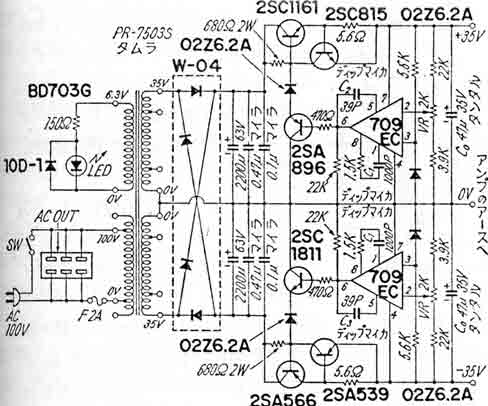
The Super Regulator from 1977, design by Mr. Kaneda.
An another example can be found in book written by Mr. Kaneda from 1977. What has changed since then? The zener references are nowadays much, much better and the opamps are even more much better. In other words there are great opportunities to increase the performance. One more change, rather important also is that the 680 ohms resistor at the top is changed to a constant current generator. This is very important for the output current capability also to the bandwidth, the speed of the regulator.
Is "Super" too much?
Does the design deserve the epithet "super"? Yes, indeed! Can anyone come up with any regulator with less noise and lower output impedance? I don't think so. I would be happy if someone can prove me wrong. This design is extreme in the true sense when it comes to these two parameters. I believe that a couple of more parameters also are state of the art.
I think this design is very interesting from an engineering point of view, a challenge to make it as good as it can be. Therefore I have decided to have it for spin.
Andrew L Weekes ALW has made a very good hole mounted pcb together with a very good documentation. He has also had a group purchase run at www.diyaudio.com and he came up with 700-800 pcb's, but he has left the DIY scene years ago for other activities but you can get his boards though.
aos (Andrija Ifkovic), has also made an pcb to a very good price but has stopped selling pcb's.
BrianGT (Brian Bell) has integrated the regulator in his DAC design. The thread is here. The design did never leave the computer.
The diyaudio.com user Coffin's friend has also made two pcb's, can't say how good they are but they looks nice at least.
There are also a couple of commercial sources, really expensive ones.
