The design
Input coupling capacitor
The design is based on the datasheet of the DRV134/DRV135. The input may go via a coupling capacitor and the pcb has room for lot's of different kinds of caps. The input impedance of the DRV134 is exactly 10 kohms and you don't have to have any pulldown resistors since the inside of the DRV134 consists of inverting opamps where the input bias currents will go from the output via feedback resistors.
 |
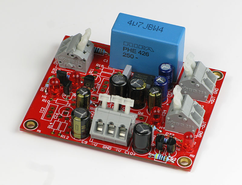 |
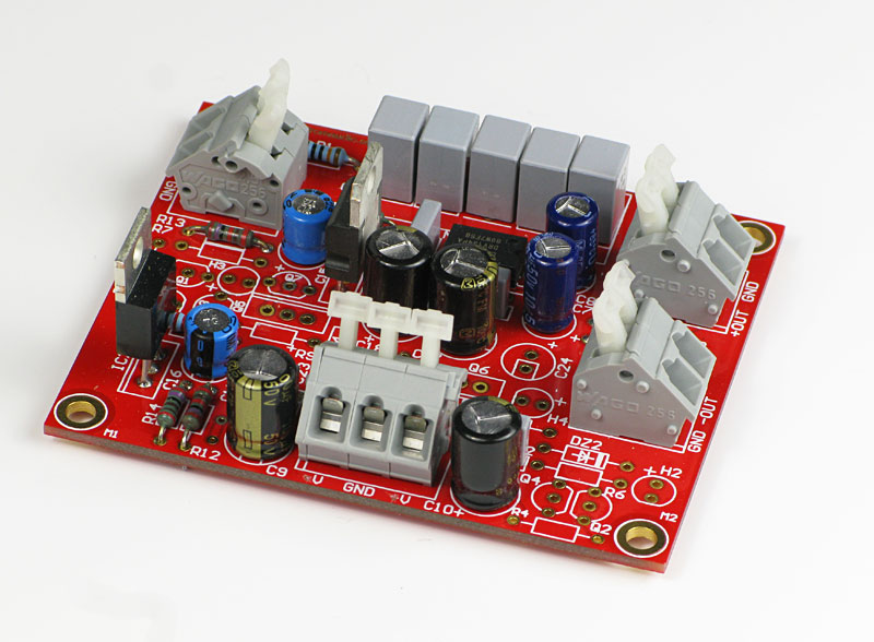
| The driver board with LM317/337 regulators. | The driver board with discrete regulators. |
Click on the picture to get a larger view.
The common mode output impedance
The DRV134 has two sensing inputs and they are for creating a high common mode output impedance which is essential for balanced signals. Texas Instruments recomends unpolarized caps for this if you also have offsets in the signal. If you have control over the situation you can short the caps with the a tin blob at the solder side.
The output impedance
The output impedance is set to 50 ohms by internal resistors but can be tuned to anything, therefore there is room for external resistors for setting the output impedance. If you not want to use those, just short them on the solder side.
DIL08 vs. SO08
The pcb has two footprints, one for DRV134 which comes in DIL08 package, holemounted and SO08 which will fit the DRV135 which is the SMD version of the DRv134. The are indentical except for thermal properties.
The power supply
The pcb has two types of power supplies. In most cases the LM317/LM337 based power supply will do. Max input voltage will be approx. 50 V DC unless you use the HV version which will manage 65 V at least. If you of some reason want to use the amplifier supply voltage the other regulator can handle 80-100 V depending of used parts. This regulator is built with a constant current source feeding an zener diode of 15 volts. This reference voltage is fed into an emitter follower formed by a TO92 or TO220 transistor. The LED's are shining rather weak because they are biased with 2.7 mA and the purpose is that they create a 1.6 V for the current generation.
Hum problems
You should pay attention not to create ground loops and by that induce hum. In some cases it may be necessary to let this driver have a separate transformer. If you are going to get hum or not can be hard to tell but feeding this pcb from a separate power supply is a safe way to succeed but you may get a hum free installation using the raw voltage from the power amp.
