RFB-02 for the power amp
The diodes for a power amp needs to be mounted on some kind of heat sink. It is not much space in my power amp so I figured that an assembly of one RFB-02 on each side of a Al plate would be good idea. As I wanted to be able to screw PCB stand-offs into the Al heat sink it needed to be thick. I used a 15mm solid Al plate and mounted 4 IXYS (60A, 200 V) Schottky diodes on each side of the plate. I made four 2.2 mm holes using the drill template I made. These holes go all the way through the Al plate. Then I threaded these 2.2 mm holes. Beware, that you should not make the threading go all the way through the hole from only one side as you will then not be able to screw standard screws into the 4 counter threaded holes on one side! One has to make the threads first for one side (around 6 mm deep) and then make the threads for the other side from the other side.
The diodes are mounted in pairs, that is I made only one hole (without threading them) for each pair of diodes. A long M3 screw then finishes the diode fastening. Isolation washers made out of silicone were used for short circuit prevention.
As I used Schottky diodes the snubbers are not necessary. These types of diodes do not have any recovery problems as other diodes have. I think that snubbers on Schottky diodes can even make things worse by introducing ringing.
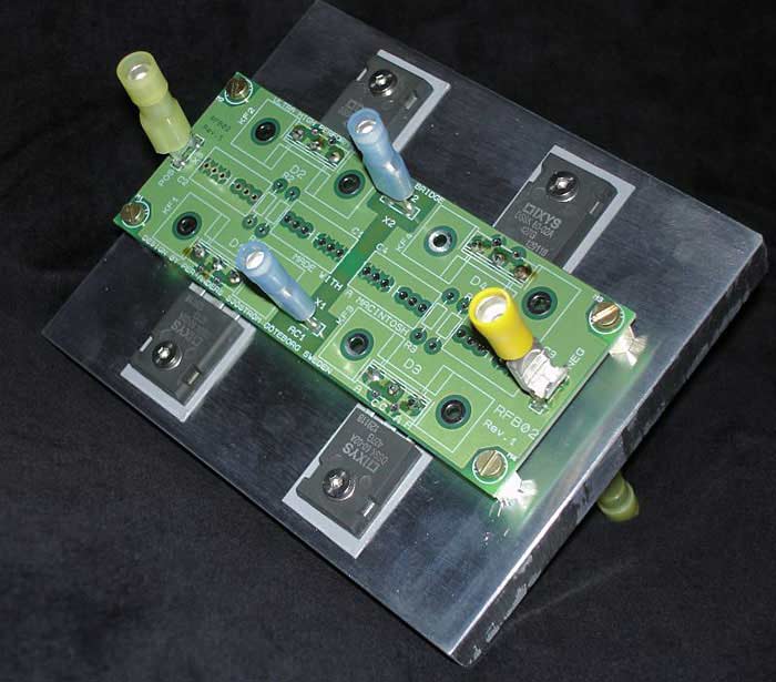
Figure 3 Power amp rectifiers. Snubbers not used. Plenty of space on the PCB. This space will be used for the AC filter capacitors.
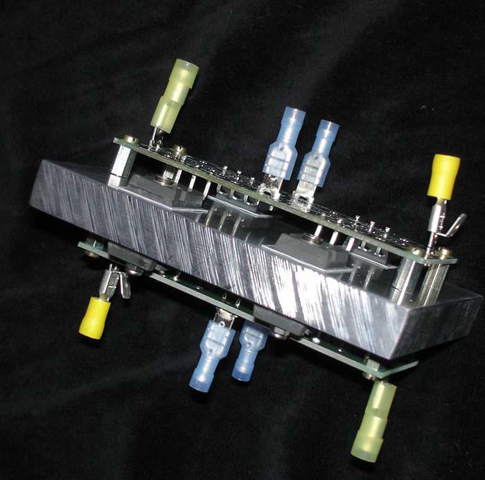
Figure 4 Another view shows the dual RFB-02s. Note the right spade plug. It is a dual one which will be used to make the ground connection.
The assembly looks rather nice, and the share weight of it makes it feel good! The mass of the Al plate is of course not necessary for cooling purposes. The heat sink plate area is the most important thing when it comes to cooling the diodes.
It is made for a power amp, and this bridge of mine really fits well into a huge power amp like I have .
Now, where to fit the four capacitors for AC filtering and one for DC filtering? A look at figure 5 shows that there is plenty of space where the four pair of snubbers and four heat sinks usually are to be fitted.
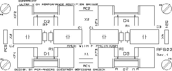
Figure 5 Stuffing guide for RFB-02.
To be able to solder the four X2 capacitors, one has first to scrape off some green laquer around the holes for KF1-KF4 (intended use for diode heat sinks) so there is some bare copper to solder onto. The holes for KF1-4 are used for the X2 capacitors!
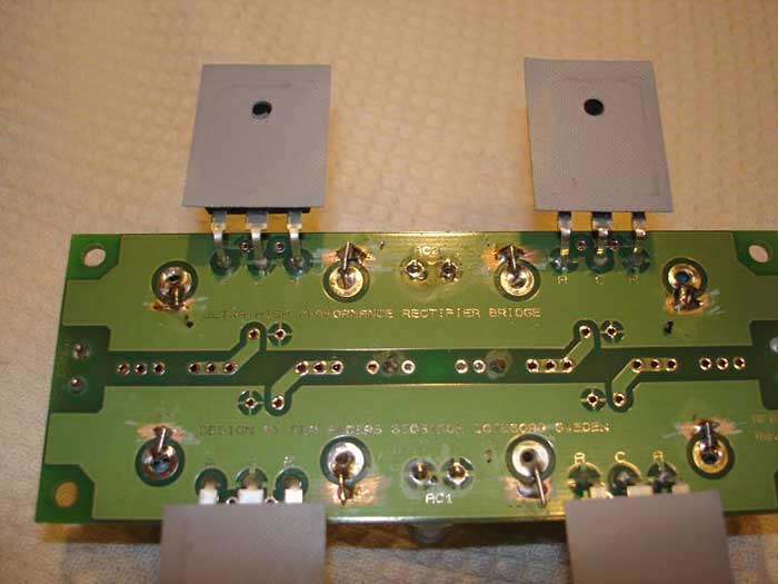
Figure 6 The PCB has been scraped and the extra capacitors are soldered.
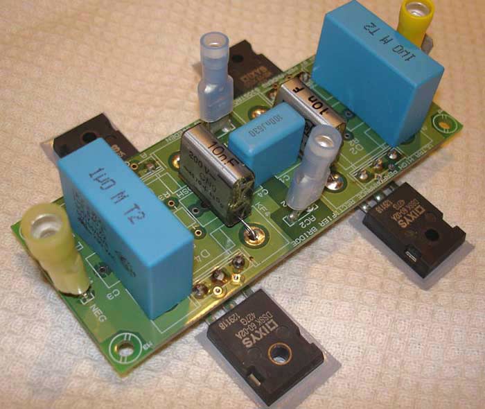
Figure 7 The four X2 capacitors and the DC voltage filtering capacitor are mounted. The PCB is now finished.
Figure 7 shows how well the larger X2 capacitors fit into the holes for KF1-4. The smaller (10nF) capacitors do not fit as well as the larger ones, but it was easy to fit them anyway. The PCB is now finished. It is a heck of a rectifier/filtering unit!
