The schematics
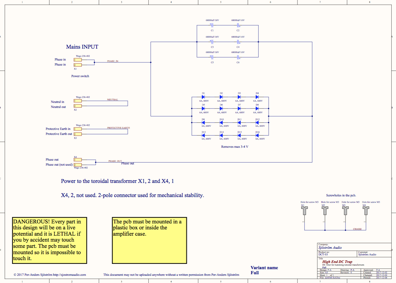
Click on the picture to get a larger view. The picture shows the schematics of the amp. Of course you can't use it for anything except for an overview. Please download the pdf-file instead if you want to see the details.
WARNING - CAUTION
As you can see at the picture the pcb will be at mains potential and therefore lethal. You must insure that this pcb is well protected against unintentional touching. All parts are dangerous to touch when the mains is switched on.
Circuit description
This design is very simple, just a couple of diodes and capacitors. The purpose of the diodes is to limit the DC voltage across the caps, especially at high load and at power on. The pcb contains of 16 diodes where there are two in parallel for each direction. This is for increasing the current capacity to the double. Normally you should not connect diodes in parallel in they not are on the same die but in this case I think it will work fine since they will have the same temperature and will most likely not continuously carry any larger currents. I recommend that you solder all 16 diodes. The only disadvantage is a slightly higher cost. Don't try to desolder. You will only damage the pcb.
The capacitor impedance determined by:
Z = 1/(2*pi*f*C)
where
f = mains frequency, 50 or 60 Hz
C = capacitance in Farads
Maximum current without passing the diodes:
Max Irms = 0.7*U*2*pi*f*C
where
U = the voltage when current is flowing through the diodes which also can be tranzils. In my case 0.7, 1.4, 2.1 or 2.8 Volts
C = capacitance. If six 68000 uF are used the capacitance will be 102000 uF.
f = mains frequency, 50 or 60 Hz
X1 and X4 are 2-pole just because they are separated and the connector has two poles. No need for the extra pole really.
I have added room for three wires in and three wires out. Neutral and Protective Earth can be connected also just as a joint between incoming mains cable and the internal wiring.
| Terminal | Pin | Name | Incoming power | To transformer | Notes |
| X1 | 1 | Phase in | X | - | |
| X1 | 2 | Phase in | - | - | Not used, only for mechanical stability. |
| X2 | 1 | Neutral in | X | - | |
| X2 | 2 | Neutral out | - | X | |
| X3 | 1 | Protective earth in | X | - | |
| X3 | 2 | Protective earth out | - | X | Connected to chassis. The incoming wire could also be connected directly to the chassis. |
| X4 | 1 | Phase out | - | X | |
| X4 | 2 | Phase out | - | - | Not used, only for mechanical stability. |
